

Electrical characterization of a ceramic with MTZ-35 and HTSH-1100 test fixture Material Science – Application Note 1
Latest updated: June 11, 2024Abstract
Impedance spectroscopy is a powerful and non destructive method for characterization of electrical properties of material.
In this note the electrical properties of 5 mol% Yttria Stabilized Zirconia (ZrO2)1-x (Y2O3)x with x= 0.05 have been investigated by impedance spectroscopy in the temperature range 600°C-900°C using MTZ-35, HTF-1100 and HTSH-1100. Bulk, grain boundary and total conductivity vs. inverse temperature were plotted. The activation energy associated with each conduction mechanism was also determined.
Introduction
Impedance spectroscopy is a powerful and non-destructive method for characterization of electrical properties of materials. These properties can also be temperature dependent, which necessitates a temperature control unit and sample holder for accurate and complete characterization.
Yttria Stabilized Zirconia system was chosen as an example of solid electrolyte material for this note. This ceramic is commonly used as an electrolyte material in solid oxide fuel cells (SOFCs) and electrochemical sensors [1-2].
In the present note the electrical properties of 5 mol% Yttria Stabilized Zirconia (ZrO2)1-x (Y2O3)x with x=0.05 (denoted here as 5YSZ) have been investigated by impedance spectroscopy. The through-plane conductivity (conductivity along the perpendicular direction to sample surface) of 5YSZ at temperature ranging from 600 °C to 900 °C was measured by the MTZ- 35 Impedance analyzer, High Temperature Sample Holder HTSH-1100 and High Temperature Furnace HTF-1100. The main purpose of this note is to give details on how to use the MTZ-35, HTF-1100 and HTSH-1100 for the measurement of ionic conductivities and activation energy associated with each ionic conduction mechanism. The measured conductivities and activation energies were compared to published literature values.
Experiment
Commercial 5 mol% Yttria stabilized zirconia sample 5YSZ (Goodfellow, UK) was tested as a solid electrolyte. The sample was a square plate of 5YSZ with a size of 25x25x1 mm3.
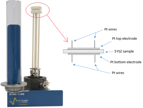
The 5YSZ sample was set between the 12 mm diameter Platinum discs of HTSH-1100 as shown in the Fig. 1.

Figure 1: Scheme of the 5YSZ sample installed on the HTSH-1100 test fixture.
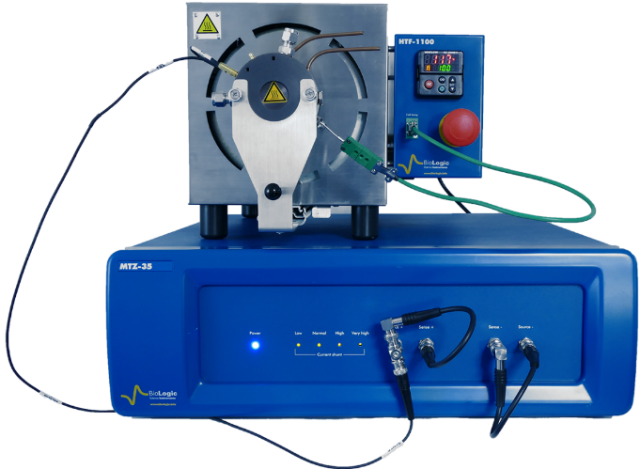
The HTSH-1100 was placed in the HTF-1100 furnace and connected to MTZ-35 using a two-terminal connection (Fig. 2). The furnace and the sample temperatures were controlled by MT-Lab® software using a heat-up rate of 10 °C/min. Both temperatures were measured by two K-type thermocouples incorporated into HTF-1100 and HTSH-1100.

Figure 2: Experimental setup.
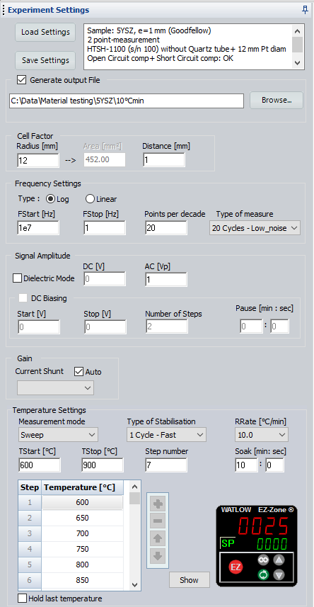
Impedance measurements were carried out on the sample by means of a BioLogic impedance analyzer (MTZ-35) over the frequency range of 10 MHz-1 Hz with an AC voltage amplitude of 1 V. As the measurements were not conducted under controlled atmosphere, the sealed quartz tube of HTSH-1100 was not used. Impedance diagrams were recorded in 50 °C intervals between 600 °C and 900 °C. Fast temperature stabilization mode was used in MT-Lab® software for the stabilization of the sample temperature at each measurement point. After the temperature stabilization, an additional dwell time (soak time) of 10 min was set to ensure steady state conditions at each measuring point (Fig. 3).

Figure 3: Screenshot of the experimental parameters set in MT-Lab® software.
Prior to these impedance measurements, open-circuit and short-circuit compensations were performed by MT-Lab® software in order to remove stray impedances due to HTSH-1100 sample holder and cell cables. More details on the open and short-circuit compensations procedure are given in the MTZ-35 manual and in the technical note TN#01 [3].
Impedance data evaluation and equivalent electrical circuits modeling were done with Z Fit analysis tool available in MT-Lab® software (Fig. 6).
Once the electrical parameters were determined by Z Fit, the ionic conductivities of the 5YSZ sample in air were computed and plotted as a function of temperature.
Results & Discussions
Impedance data
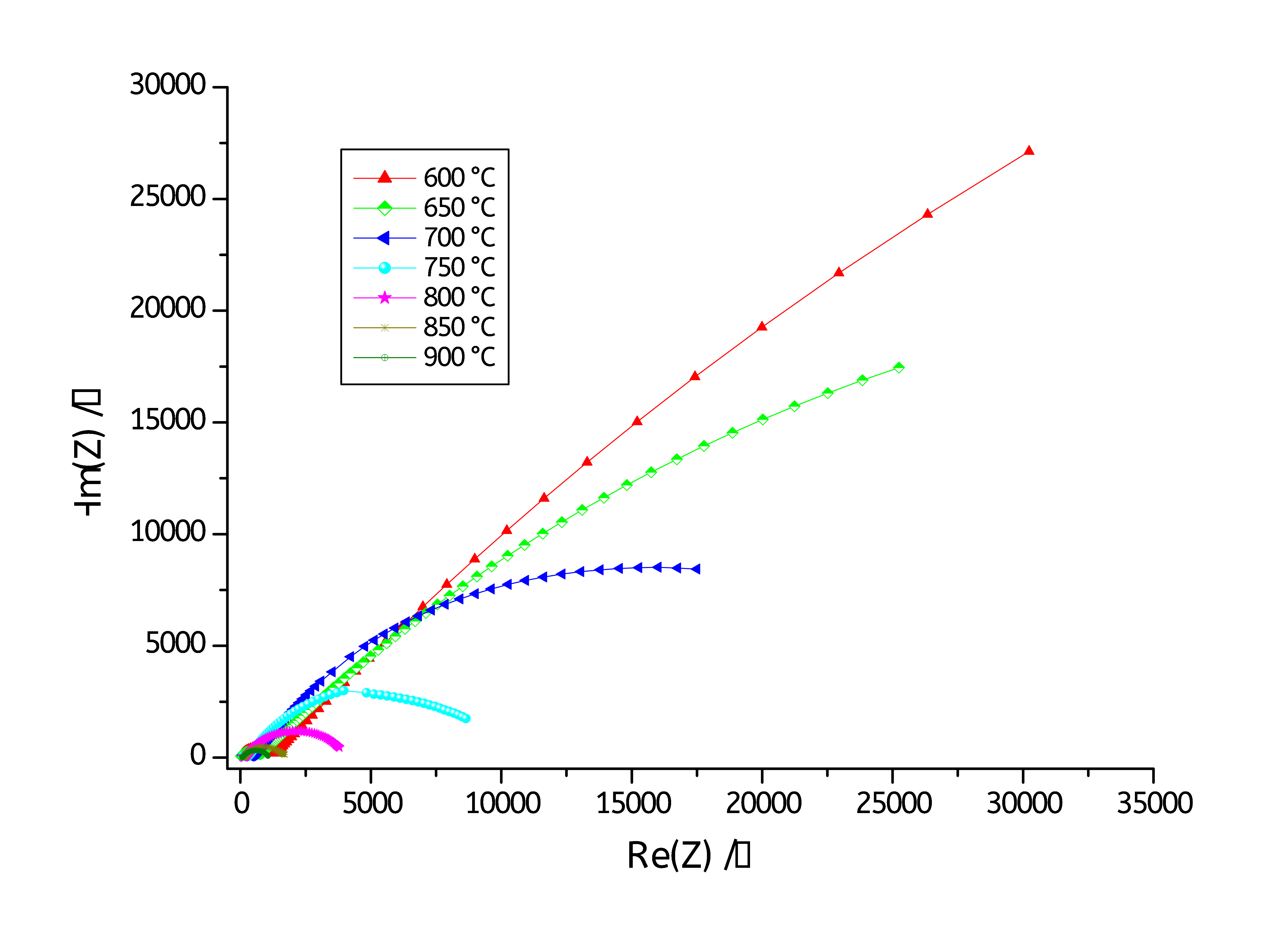
The impedance of 5YSZ electrolyte at different temperatures were measured by MT-Lab® software. Fig. 4 shows the temperature-dependent Nyquist plots of 5YSZ electrolyte over the temperature range 600°C to 900°C (with a step of 50°C).

Figure 4: Nyquist plots of 5YSZ in the temperature range between 600°C and 900°C.
A zoom on the high frequencies region is shown in Fig. 5.

Figure 5: Zoom on the high frequencies region.
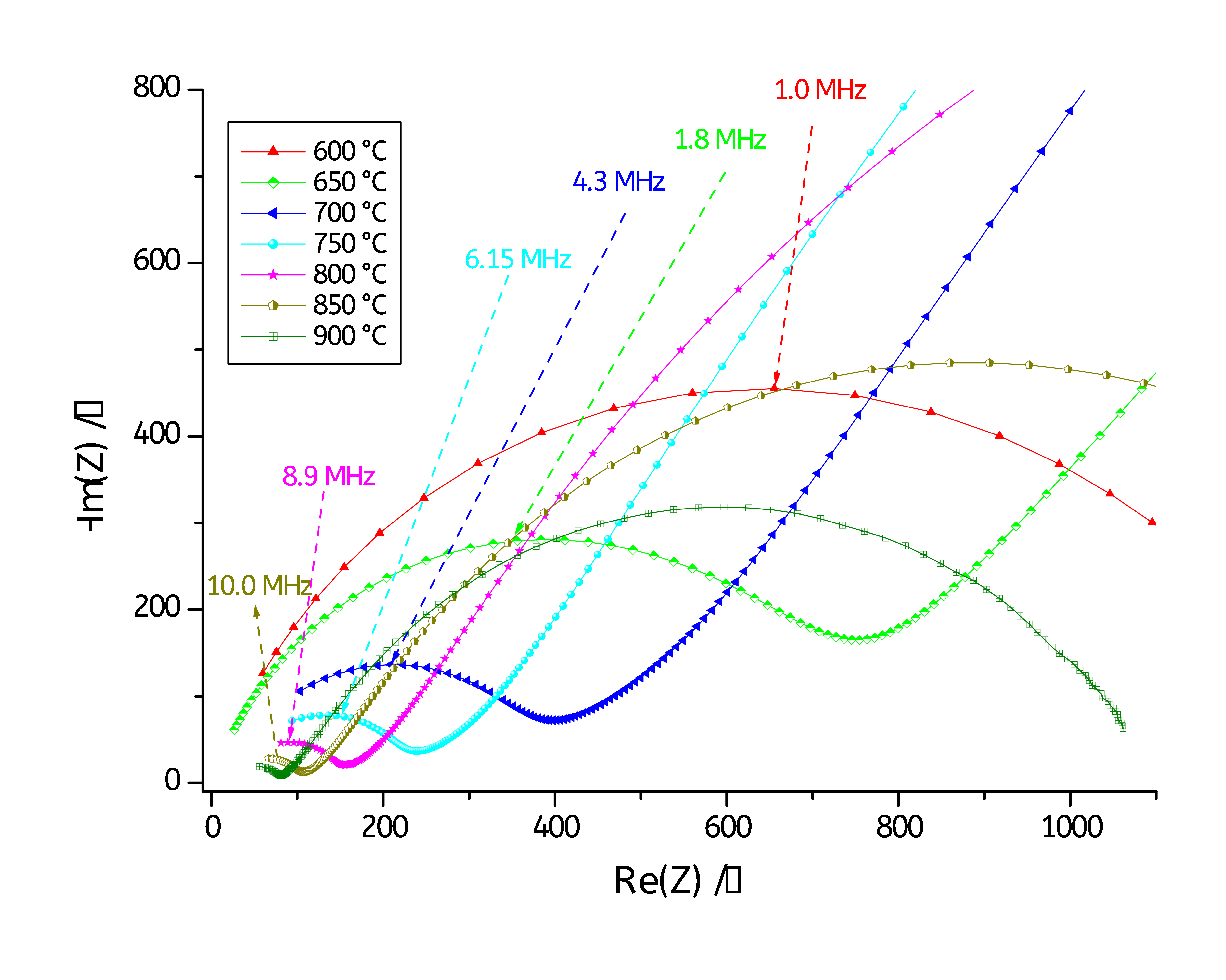
Figs. 4 and 5 show Nyquist diagrams recorded at various temperature ranging from 600°C to 900 °C. The Nyquist diagrams reveal two main semicircles: one at low frequencies and a second one at high frequencies. The high frequencies semicircle is associated with the bulk (or grain) conductivity response, while that at the low frequencies is attributed to grain boundary conduction contribution [4-6].
The total conductivity of the 5YSZ is due to the contribution of two ionic conduction mechanisms: bulk conduction and grain boundary conduction [7,8].
Impedance modelling
The impedance diagrams of 5YSZ were fitted using Z Fit analysis tool available in MT-Lab® software (Fig. 6).

Figure 6: Z Fit tool of MT-Lab® software.

As it can be seen on Figs. 4 and 5, the two semicircles of each Nyquist diagram are depressed, so each semicircle was fitted to a resistor in parallel with a Constant Phase Element (CPE) instead of a capacitance (C). The CPE impedance (ZCPE) is defined as below [9]:
$$Z_\text{CPE}=Q^{-1}(j2\pi f)^{-\alpha}\tag{2}$$
Where ZCPE is the complex impedance, Q is the CPE with the unit F sα-1, $f$ is the frequency, α ϵ [0, 1] and j the imaginary number j = (-1)1/2
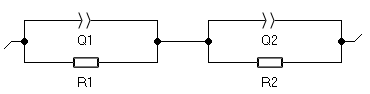
As all the impedance diagrams exhibit two depressed semicircles, all the diagrams, obtained for temperature between 600 °C and 900 °C were fitted to the same equivalent circuit model of the Fig. 7. This circuit consists of R1/Q1+R2/Q2: R1/Q1 models the grain conduction and R2/Q2 represents the conduction through the grain boundaries.

Figure 7: Equivalent circuit.
The capacitances C were estimated from the constant phase element of the grain and the grain boundaries using the pseudo capacitance tool “PseudoC” (Fig. 6) based on the equation below [9]:
$$C=Q^{-1/\alpha}R^{(1/\alpha)-1}\tag{3}$$
where Q and R are the fitting parameters. α is the number associated to CPE parameter α ϵ [0,1].
CG and CGB represent the dielectric effect in the grain and grain boundary regions respectively. The dielectric constant ɛ’ can be estimated from the grain and the grain boundary capacitances. They can also be used for the estimation of the thickness of the grain boundary region [4, 11].
The results of the measured resistance and the calculated capacitances are summarized in Tab I.
Table I: summary of the best fitting resistances and capacitances values obtained by Z Fit.
| T/°C | RG/Ω | RGB/Ω | CG/nF | CGB/µF | RTot/Ω |
|---|---|---|---|---|---|
| 600 | 1225 | 216756 | 4.90 | 7.73 | 2.2 1005 |
| 650 | 700 | 96843 | 7.60 | 9.21 | 9.8 1004 |
| 700 | 472 | 32192 | 8.65 | 8.58 | 3.3 1004 |
| 750 | 248 | 10056 | 5.32 | 5.32 | 1.0 1004 |
| 800 | 124 | 4143 | 2.73 | 10.63 | 4.3 1003 |
| 850 | 65 | 1327 | 4.00 | 13.65 | 1.4 1003 |
| 900 | 27 | 616 | 0.96 | 16.53 | 6.4 1002 |
Table I shows that the electrical resistances from the grains boundaries are higher than those from the grains. Both resistances decrease with increasing temperature which is in agreement with Arrhenius law behavior.
Table 1 also shows that conduction through the grains of the 5YSZ is characterized by low capacitance values whereas the conduction through the grain boundaries has a relatively higher capacitance [4].
Ionic Conductivities
On basis of the fitted equivalent resistors, the conductivity of the grain, grain boundary and the overall conductivity were evaluated from the fitting resistance RG, RGB and RTot.
Bulk conductivity, grain boundary conductivity and total conductivity of 5YSZ (denoted by σG, σGB and σTot respectively) were calculated for each temperature according to the equation (4), (5) and (6) respectively:
$$\sigma_\text{G}=\frac{4\,e}{\pi d^2R_\text{G}}\tag{4}$$
$$\sigma_\text{GB}=\frac{4\,e}{\pi d^2R_\text{GB}}\tag{5}$$
$$\sigma_\text{Tot}=\frac{4\,e}{\pi d^2(R_\text{G}+R_\text{GB})}\tag{6}$$
Where:
e is the sample thickness (e=1 mm).
pd2/4 is the active sample area (contact area with Pt disc) with d is the Platinum electrode diameter (d=12 mm).
RG is the bulk resistance.
RGB is the grain boundary resistance.
RG+RGB is the sum of the bulk and the grain boundary resistances.
Table II presents the values of the bulk, grain boundary and the total ionic conductivities of 5YSZ at the seven studied temperatures.
Table II: summary of conductivities at several temperatures.
| T/°C | σG/S cm-1 | σGB/S cm-1 | σTot/S cm-1 |
|---|---|---|---|
| 600 | 7.22 10-05 | 4.08 10-07 | 4.06 10-07 |
| 650 | 1.26 10-04 | 9.13 10-07 | 9.07 10-07 |
| 700 | 1.87 10-04 | 2.75 10-06 | 2.71 10-06 |
| 750 | 3.56 10-04 | 8.80 10-06 | 8.58 10-06 |
| 800 | 7.13 10-04 | 2.14 10-05 | 2.07 10-05 |
| 850 | 1.36 10-03 | 6.67 10-05 | 6.35 10-05 |
| 900 | 3.28 10-03 | 1.44 10-04 | 1.38 10-04 |
Table II shows that the grain boundary conductivity is significantly smaller than the grain conductivity. Similar results were observed by Daeland and al. [4] when they studied 4YSZ system. The grain boundary conductivity is around two orders of magnitude lower than the bulk conductivity. This result was also observed in the references [8, 10].
In other studies, it was observed that at low temperature the total conductivity is dominated by the grain boundary conductivity. However, the grain boundary conductivity contributes less to total conductivity than the bulk conductivity at high temperatures [7]. W-J. Ning and all have shown that electrical conductivity of 4.5YSZ is dominated by grain conductivity at temperature higher than 700 °C-750 °C [6].
The literature ionic conductivity values depend on the Yttria content, the composition, the microstructure YSZ system, the impurities (Si, Al, etc) and on the manufacturing/synthesis method. Many publications were focused on 8 mol% YSZ which is the standard YSZ material used for electrolytes due to its higher ionic conductivity however a few papers dealt with 5YSZ. Globally the measured ionic conductivities of 5YSZ are at least one to two orders of magnitude lower than the conductivity values published in the literature which vary from one paper to another. A microstructural characterization of the 5YSZ (grain size, impurities, etc) could help to explain this difference.
Bulk, grain boundary and total ionic conductivity vs. inverse temperature (1000/T) diagrams were plotted and displayed in Fig. 8.
Figure. 8: Arrhenius plot for grain (a), grain boundary (b) and total conductivities (c).
One can see that the plots of the Fig. 8 are linear (linear regression Fit with a good accuracy R2=0.98). The bulk, grain boundary and total conductivities follow the Arrhenius law relating ionic conductivity, σ, and absolute temperature, T (7):
$$\sigma=\sigma_0\exp\left(\frac{-E_\text{a}}{K_\text{b}\, T}\right)\tag{7}$$
where
– σ is the ionic conductivity.
– σ0 is the pre-exponential factor.
– Ea is the activation energy (J).
– Kb the Boltzmann constant (1.38 10-23 J/K).
– T is the absolute temperature (K)
Assuming that conductivity plot continues to be linear outside the temperature range 600-900 °C, the conductivity of the 5YSZ can be predicted and estimated at temperature lower than 400 °C and higher than 900 °C. These conductivities can be obtained by extrapolation of the Arrhenius plots at low and high temperatures.
Activation Energies
Conductivity vs. reciprocal of temperature plots of bulk, grain boundary and total ionic conductivity of 5YSZ electrolyte are shown in Fig. 8. Each plot was fitted with a straight line. The activation energies EG, EGB and ETot were deduced from the slope of σG, σGB, and σTot conductivity plots, respectively. The activation energy gives information about the amount of oxygen free vacancies and the mobility of these vacancies in the 5YSZ electrolyte. The activation energies of oxygen conduction for 5YSZ are listed in the Tab. III.
Table. III: Summary of activation energies of 5YSZ.
| Conduction mechanism | Ea/J | Ea/ev |
|---|---|---|
| Bulk conductivity (EG) | 1.75 10-19 | 1.09 |
| Grain boundary conductivity(EGB) | 2.84 10-19 | 1.77 |
| Total conductivity (ETot) | 2.82 10-19 | 1.76 |
The activation energy for bulk conductivity mechanism (1.09 eV) is in good agreement with the bulk activation energy value measured on 4.5 YSZ by Ramamoorthy and al [11] where an activation energy value of 1.12 eV was measured. However, for grain boundary and total conductivity, the measured activation energy for 5YSZ is slightly higher than the activation energy value given in the reference [11] where a value of is 1.27 eV was obtained for 4.5YSZ.
The conductivity vs. inverse of temperature plot could also be fitted with two separate straight lines (two closes slope values) or with a second order polynomial. In this situation the activation energies can be calculated at two temperature ranges or at each temperature individually.
Conclusion
Through-plane conductivity of 5 mol% Yttria Stabilized Zirconia electrolyte (5YSZ) was investigated by Impedance spectroscopy using MTZ-35 impedance analyzer, HTSH- 1100 and HTF-1100 furnace. The oxygen ion conductivities were calculated from impedance data and sample geometry. The results showed a mixed bulk and grain-boundary conduction mechanism in the temperature range between 600 °C and 900 °C.
The activation energy for bulk conductivity agreed well with the literature value (EG= 1.09 eV) whereas those of the grain boundary and the total conductivity were slightly higher than the literature values. Impedance data must be correlated with other experimental information, such as structural characteristics (XRD, SEM, EDS, etc).
The measurement accuracy can be improved by the metallization or by the application of a very thin film of a conductive paste or ink on both sides of the sample in contact with the platinum electrodes of the HTSH-1100. Platinum paste is recommended for our temperature conditions (600 °C- 900 °C). However, this operation is not recommended for porous material samples where a diffusion of the conductive paste/ink through the pores can occur at high temperature, and could lead to a short circuit and erroneous measurements.
References
1) A. Karthikeyan, C-L Chang, S. Ramanathan, Applied Physics Letters, 89, (2006) 183116.
2) F.C. Fonseca, R. Muccillo, Solid State Ionics 166 (2004) 157.
3) TN#1: cell cable and sample holder compensation.
4) D. Maeland, C. Suciu,I. Wærnhus, A.C. Hoffmann, J. Eur. Ceram. Soc. 29, (2009) 2537.
5) R. A. Gerhardt. In G. L. L. P. W. Franco, B. (editor), Encyclopedia of Condensed Matter Physics. Elsevier, Oxford (2005)350.
6) X.-J. Ning, C.-X. Li, C.-J. Li, G.-J. Yang, Vacuum 80 (2006) 1261.
7) C. Zhang, C.-J. Li, G. Zhang, X.-J. Ning, C.-X. Li, H. Liao, C. Coddet, Mater. Sci. Eng. B, 137 (2007) 24.
8) M. Gerstl, E. Navickas, G. Friedbacher, F. Kubel, M. Ahrens, J. Fleig, Solid State Ionics 185 (2011) 32.
9) AN#20 Pseudocapacitance calculation, http://www.bio-logic.info/asets/app%20-notes/20101209%20-%20Application%20 note%2020.pdf
10) C. Peters, A. Weber, B. Butz, D. Gerthsen, E. Ivers-Tiffee, J. Am. Ceram. Soc. 92 (9) (2009) 2017.
11) R. Ramamoorthy, D. Sundararaman, S. Ramasamy, Solid State Ionics 123, (1999) 271.


