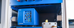
ITS-e (Intermediate Temperature System).
An EC-Lab compatible compact/small-footprint benchtop temperature chamber for the electrical characterization of materials.
Accurate temperature control between - 35 °C and + 150 °C and compatibility with BioLogic's benchmark control and analysis software, EC-Lab.
A small-footprint benchtop temperature chamber
The intermediate temperature system allows accurate temperature control between -35°C and +150°C. This is a good alternative to the larger conventional climatic chambers available on the market. Thanks to its small chamber, the temperature homogeneity is much better than in conventional chambers and leads to more reproducible measurements.
Application oriented
The ITS-e is designed to accommodate the leak-tight BioLogic sample holders CESH and CESH-e for the electrical characterization of hard, powdered, pasty and soft materials.
It can also be used for thermal curing and aging and for the determination of some kinetic or thermodynamic parameters like activation energy, phase transformation or glass transition temperatures.
It is also compatible with the liquid conductivity kit used with HTCC conductivity cells dedicated to gel and liquid materials.
Fully integrated and compatible with BioLogic products
The ITS-e is compatible with the MTZ-35 impedance analyzer and with BioLogic potentiostats. It allows users to easily set up their electrical and electrochemical experiments thanks to EC-Lab and MT-Lab software.
From solid to liquid samples
The ITS-e temperature system can be used with solid and liquid sample holders for accurate conductivity measurements.
For more information, visite the CESH-e (enhanced controlled environment sample holder) or HTCC web pages.
ITS-e Software
The ITS-e is controlled via a USB connection using EC-Lab or MT-Lab® software. Ethernet communication is also available with EC-Lab software through the TCU server. This allows the remote control and sharing of the ITS-e among many users through a LAN network.
MT-Lab® and EC-Lab® software offer intelligent temperature management with various temperature control modes.
MT-Lab® and EC-Lab® interfaces provide protocols and data graphing for impedance measurement and data processing. The impedance data can be fitted using the powerful Zfit tool available in both software.
Specifications for the ITS-e small footprint temperature chamber
- Operating temperature range: – 35 °C to + 150 °C(*)
- Temperature accuracy: ± 0.3 °C
- Computer Interface: USB or Ethernet
- Mains voltage: 115 V/230 V 50/60 Hz
- Power consumption: 250 W
- Dimension: 400 x 313 x 385 mm (L x W x H)
- Weight: 8 kg
(*): For a control vs. Tsample
In the ITS’s brochure, two PT-1000 are mentioned to be provided with the ITS? I received only one PT-1000. What about the second PT-1000?
Two PT1000 are provided by default with ITS. The first one (not visible) is installed inside the ITS for measuring the ITS temperature and the second one is expected to be connected to CESH sample holder.
I cannot connect ITS to MT-Lab® software?
First check if the ITS is seen by the operating system of your computer by clicking on “Control Panel” > “Device Manager”> “Ports (LPT & COM)”. If you see “communication device class ASF example (COM X)”. This means that the USB driver is working. In case you cannot see it, that means that the ITS driver was probably not well installed. Re-install MT-Lab® software and the ITS driver.
Can I use ITS with another impedance analyzer?
ITS is controlled by MT-lab® software only if MT-lab software is connected to MTZ-35 impedance analyzer. It can also be controlled by EC-Lab® software connected to potentiostat.
Can I control the ITS manually?
No
How can I control ITS with a potentiostat?
An ITS can be controlled by a BioLogic potentiostat through the analog output using a DB9-DB9 cable. The user has to load Temperature Control (TC) protocol and to go to “External Devices” tab of EC-Lab, select “TCU” in the device type and ITS as a device name in order to control the temperature of the ITS. More details can be found in the Operating manual for ITS.
I performed impedance measurement at various temperatures with MT-Lab® software. The temperatures displayed on the impedance plots are the setpoint temperatures. How can I access to the actual temperatures at which the impedance measurements have been performed?
You can access to the actual sample’s temperature at which the impedance measurement has been performed by selecting “Data” tab in the graphic window of MT-Lab® software and then select “sample temperature” column.
How can I access to the coordinates (frequency, phase, etc) of a measured point of impedance diagram?
You can access to the coordinates of a measured point by clicking on “Data view”. A data view window is displayed. In case of multi- temperature graphs, select the graph at the desired temperature and the impedance representation and then click on the point you want to display the coordinates. “Data view” is disabled during data acquisition.
I bought an additional PT1000 to monitor the temperature of the sample. Can MT-lab® control the temperature versus the Tsample or it still control the temperature versus the Tcell even if a second PT1000 is connected to ITS?
MT-Lab controls the temperature versus Tcell even if a Tsample is displayed on the temperature plot. If you want to control the temperature versus the sample temperature the PT1000 placed in the central hole of the CESH, close to the sample has to be plugged in the “TCell” Lemo connector on the rear panel of the ITS.
I use In-plane CESH with interdigitated electrode. What is the nominal constant of this electrode?
The nominal constant of the interdigitated electrode is 0.2 cm-1. This constant can be determined using a standard solution. More details can be found in the TN#06 – Calibration of a sample holder.


