Reduce parasitic impedance on high impedance measurements
Latest updated: December 20, 2024Introduction
Impedance measurements are used for determining key parameters essential for understanding electrochemical systems. Some applications require measurements at high frequencies or the capability of measuring specimens with very high impedance or small capacitance. This is particularly the case in the study of coatings (corrosion), supercapacitor electrode materials, dielectric materials (energy), insulating materials (materials science), or capacitive sensors. In these application fields, the accuracy of the measurement drastically impacts the quality of the data and the relevance of the interpretation of results. It is therefore even more important to eliminate any parasitic impedance when performing these measurements.
Impact of parasitic impedance on high-impedance measurements
An EIS measurement is performed on a metal plate covered by a high-impedance coating. Usually, high impedance samples exhibit a nearly vertical shape on the Nyquist plot, aligning closely with the imaginary axis. This occurs because the imaginary component, associated with capacitive behavior, dominates the impedance. In that case, the experimental Nyquist graph obtained appears consistent with the sample and should allow for parameter determination.
However, when switching to the Bode representation, artifacts can be observed in the phase response which are called “phase jumps”. Because of the capacitive behavior of the sample, small changes of the phase will lead to major deviations on the Nyquist plot. This will lead to incorrect parameters when fitting data to equivalent circuit.
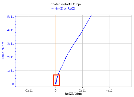
Nyquist plot
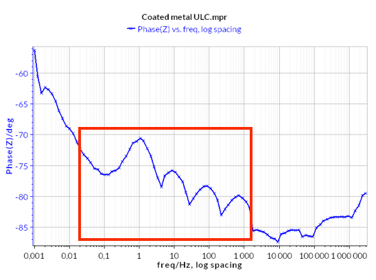
Bode plot
What are EIS phase jumps?
Phase jumps in EIS are not physical changes in the impedance of the sample. They arise due to experimental artifacts that can be linked to the setup used. High impedance/low current measurements are usually done inside a Faraday cage to prevent the measurements from being affected by external electromagnetic fields.
Parasitic impedance (usually a capacitance) is formed between the sample and the Faraday cage. This parasitic capacitance is greater in this setup, as the size of the sample is large and the distance between the sample and the metal walls of the cage is low.
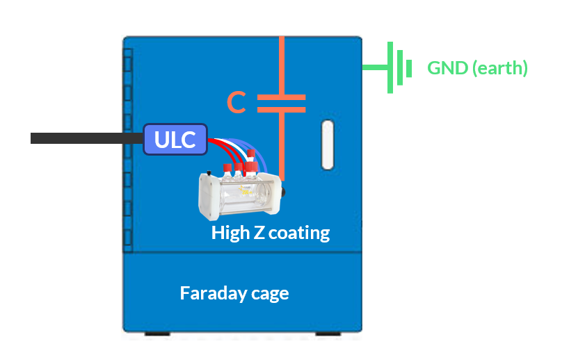
This added capacitance will affect the measured impedance and can be easily observed on the Phase Bode plot as phase jumps.
NOTE: other setup-related side effects can occur while performing EIS measurements such as inductive loops due to non-optimized reference electrodes. Learn more by reading this learning center article
Get rid of phase jumps
High impedance samples can be studied using the standard ULC option but require some setup optimizations such as shielding or using the active guard for example.
BioLogic’s ULC-z cable has been especially designed to be insensitive to capacitance between the Working Electrode and the Ground, nulling previously observed parasitic impedance. Less modular than the standard ULC option, this option is fully dedicated for EIS measurement on high impedance samples, without needing to consider using shielding methods or active guards.
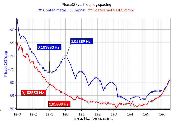
The following figures showcase the impact of parasitic impedance on the Nyquist plot obtained by measuring a coated metal. Two measurements were conducted without using shielding methods or the active guards.
- one by using a BioLogic potentiostat with a standard ULC cable (blue curve)
- one by using a BioLogic potentiostat with a ULC-z cable (red curve).
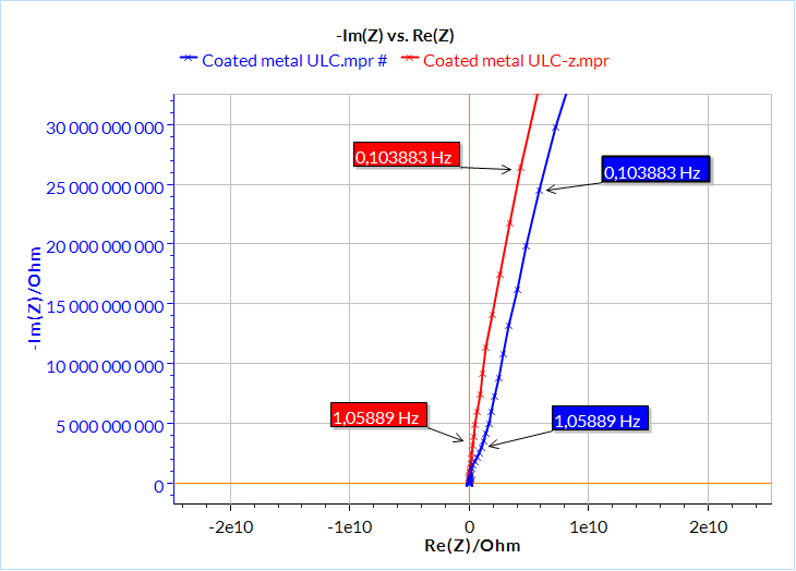
Nyquist plot
Phase Bode plot
It is noteworthy that experiments conducted with the ULC-z (red curve) demonstrate the absence of the phase jumps we observed with a standard ULC cable (blue curve). These phase jumps lead to a deviation to the right on the real axis of the Nyquist plot but are not affecting the overall shape.
Conclusions
Parasitic impedance in EIS can significantly affect measurement accuracy, particularly in high-impedance systems like coatings or insulating materials. These parasitic effects can be easily detected by looking at the Bode plot as phase jumps. These artifacts, caused by the environment or the setup, lead to non-physical deviations in phase angle. Using optimized equipment, such as ULC-z options, eliminates these issues, providing more reliable data. This ensures accurate fitting and correct interpretation of key parameters critical for understanding electrochemical systems.


