

ZFit: How the sensitivity factor can help optimize the equivalent circuit
Latest updated: November 18, 2024Introduction
In electrochemical impedance measurements the χ² figure of merit is used to estimate the goodness of fit and helps in finding the proper equivalent circuit. It is generally considered that the χ² parameter decreases as the number of parameters to be fitted increases. However, adding an element to the Equivalent Circuit Model (ECM) can be detrimental to its physical interpretation. Finding the best ECM is always a trade-off between the fitting quality and the ECM simplicity.
Sensitivity factors are additional tools that can be used to find out if an element can be considered unnecessary, even though the effect of its addition on the goodness of fit can be considered positive.
Sensitivity factors are given as a function of frequency for each fitted parameter. As such, they can be used for the same purpose as the std. err. parameter but in complimentary ways: generally, an irrelevant or unnecessary parameter will have a very high std. err and its sensitivity factor will be very low or much lower than for the other parameters and constant with frequency. More details on the standard error can be found in the corresponding Learning Center article.
An insensitive parameter can be removed from the ECM.
If some parameters see their sensitivity drastically change over the frequency range, it only means that they contribute to the impedance of the system at the frequency range where their sensitivities are higher.
Sensitivity factors are given as an .mpp file for each parameter. For each .mpp file one can plot: the real part of the sensitivity, the imaginary part of the sensitivity, the sensitivity modulus and the sensitivity phase, because the impedance is a complex number.
Sensitivity files are created when fitting experimental data using ZFit and when simulating impedance data using ZSim.
In this article we will give the theoretical expressions of the sensitivity and then give a few examples to illustrate how it can be used.
This article belongs to a series of articles which all aim at helping the user finding the best equivalent circuit. This series of articles can all be found in the header article: How to choose the proper equivalent circuit?
Formulae
Let us consider the function $Z(p_i,f)$, which is the expression of the impedance for a given ECM composed of a certain number of parameters $p$ as a function of the frequency $f$.
This function is a complex number:
$$Z=\text{Re}\,Z+j\;\text{Im}\,Z\tag{1}$$
Where $j^2 =-1$
The sensitivity $s_{Z_{p_i}}$ for the $i^\text{th}$ parameter $p_i$ is given by:
$$s_{Z_{p_i}}=p_i\frac{\partial Z(p_i)}{\partial p_i}\tag{2}$$
Which is also a complex number with unit Ω.
Because the sensitivity is a complex number, we can calculate its real and imaginary parts, as well as its modulus and its phase, according to the definitions that are recalled in the Learning Center article: What is the definition of the impedance Z?
Example
Let us consider the simple equivalent circuit R1+R2/C2. This equivalent circuit can be used to model the electrochemical impedance related to a redox reaction without mass transport limitation (also named Butler-Volmer or Tafel kinetics). R1 represents the ohmic resistance, R2 the charge transfer resistance and C2 the double layer capacitance.
The impedance of such an equivalent circuit is:
$$Z(f)=R1+\frac{R2}{1+R2\,C2\, 2\pi jf}\tag{3}$$
With $f$ the frequency in Hz.
EC-Lab® automatically calculates the real and imaginary parts of the sensitivities for all three parameters, as well as their moduli and their phases.
The expressions of the real and imaginary parts of the sensitivities for all three components are given here below:
$$\text{Re}\,s_{Z_\text{R1}}=R1\tag{4}$$
$$\text{Im}\,s_{Z_\text{R1}}=0\tag{5}$$
$$\text{Re}\,s_{Z_\text{R2}}=\frac{R2-(2C2\,R2^{3/2}\pi f)^2}{(1+(2C2\,R2\,\pi f)^2)^2}\tag{6}$$
$$\text{Im}\,s_{Z_\text{R2}}=-\frac{4C2\,R2^2\pi f}{(1+(2C2\,R2\,\pi f)^2)^2}\tag{7}$$
$$\text{Re}\,s_{Z_\text{C2}}=-\frac{2(2C2\,R2^{3/2}\pi f)^2}{(1+(2C2\,R2\,\pi f)^2)^2}\tag{8}$$
$$\text{Im}\,s_{Z_\text{C2}}=\frac{-2C2\,R2^2\pi f+(2C2\,R2^{4/3}\pi f)^3}{(1+(2C2\,R2\,\pi f)^2)^2}\tag{9}$$
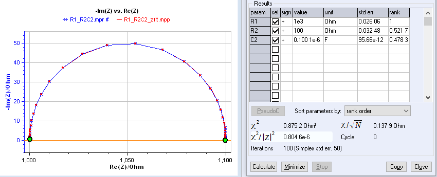
Figure 1 shows the fitting results obtained with data fitted with R1 + C2/R2 circuit. The data were simulated using ZSim, with a noise of 0.01 % |Z|.
It can be seen that the order of parameters can be chosen either in the order of the equivalent circuit or following the rank. The rank or the score is calculated using the modulus of the sensitivity and comparing which component is the most sensitive at each frequency.
Effectively, at each frequency the parameter with the lowest sensitivity modulus sees its score incremented by 1, the second lowest by 2 and so on. The final score is divided by the maximal score such that the most sensitive parameter has a rank of 1, and the others have ranks lower than 1.

Figure 1: Fit results obtained on data fitted with R1+C2/R2 equivalent circuit.
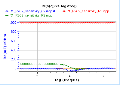
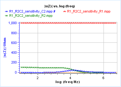
Figures 2a, 2b and 2c show the real part, the imaginary part and the modulus, respectively, of the impedance sensitivity for all three components.
Considering Figures 2a and 2c, one can see that the most sensitive component is the resistance R1, but it is only due to its high value (1000 Ω) compared to the other components. Considering Figure 2b, the least sensitive component is this same resistance R1.
a) 
b)
c) 
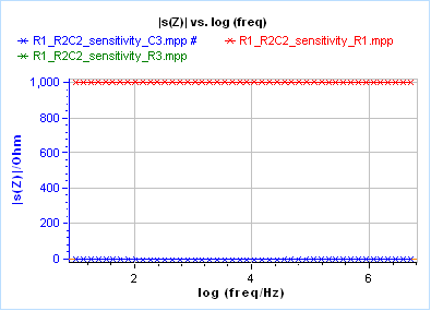
Figure 2: Sensitivities obtained when fitting data shown in Figure 1 with an R1+R2/C2 equivalent circuit.

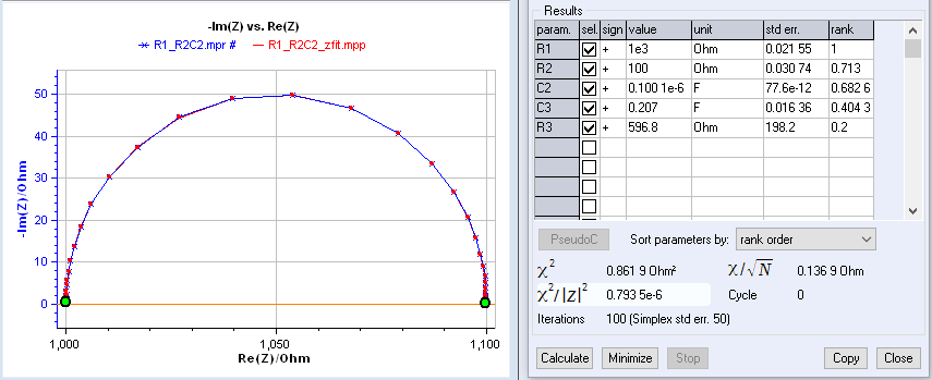
The results of trying to fit the data shown in Figure 1 with an R1+C2/R2+C3/R3 equivalent circuit are given in Figure 3. The χ²/|Z|² figure of merit is smaller in Figure 3 than in Figure 1, so based on this parameter alone one could think it is better to use the more complex equivalent circuit. However, looking at the R3 and C3 parameter values and the associated standard errors in figure 3, one could suspect something is wrong. The time constant of the R3/C3 circuit is quite large $(\tau = R3\,C3=0.207 \times 596.8 = 123.5)$, compared with the R2/C2 time constant, which means that the fitting algorithm tries to fit a semi-circle that is not even visible in the data, based on low frequency noisy data points. Looking at the very large std err. associated with the R3 parameter seems to confirm that it is irrelevant.

Figure 3: Fit results obtained on data fitted with R1+C2/R2+C3/R3 equivalent circuit.
It is only by closely looking at the sensitivities shown in Figure 4 that it can be known for sure that R3 and C3 are totally irrelevant elements. In this case, the modulus of the sensitivities of the R3 and C3 are 0 for all frequencies.

Figure 4: Sensitivities obtained when fitting data shown in Figure 4 with an R1+R2/C2+R3/C3 equivalent circuit.
Conclusion
Sensitivity factors found only in EC-Lab® provide valuable insights when selecting the most appropriate equivalent circuit model (ECM). While χ² generally decreases with more elements, a simpler ECM with high sensitivity for each parameter is often preferable for clear physical interpretation. Sensitivity values are useful in effectively identifying unnecessary elements in the ECM for a more concise and interpretable model. Together with standard error values, sensitivity factors are there to help optimize the ECM.


